


Robert Thoft Christensen
Operations Director

Semco Maritime AS
Hanøytangen 130
5310 Hauglandshella
Norway
The rack plate of the CJ70-X150 extends 100 mm beyond the chord scales, i.e. only the rack plate will be in contact with the dock bottom.
The rack plate of GustoMSC CJ70-X150 extends 100 mm beyond the chord scales, i.e. only the rack plate will be in contact with the dock bottom.
Due to this leg design, we could see that the jack-up could be suitable for dry docking at Hanøytangen. All CJ70 design units have the same footprint with three rack areas of 1050 mm x 210 mm under each leg. The centre rack steel plate has a yield strength of 690 MPa.
We made some preliminary calculations of yield and buckling loads including typical weights of hull, leg and variable load. The calculations came out with the result that margins were satisfactory. Sliding and overturning calculations all proved a very low utilisation load and were found acceptable.
Our initial intention was to place the CJ70 directly on the bottom of the dry dock. However, having checked the capacity of the bedrock it was obvious that the bedrock would not be able to withstand the load from the rack plate. We therefore installed some steel plates of various thicknesses below the rack plates and calculated the effect.
However, the preparatory phase was much more difficult than expected. The pressure at the rack contact area exceeded 30,000 tons per m2. Even with steel plates up to a height of 1,600 mm, we had difficulties transferring the rack load into the bedrock. It proved to be almost impossible to obtain a satisfactory low pressure that would be tolerated by the bedrock.
Another issue was the high steel plinths for the CJ70, which would make it very difficult to perform a normal docking operation. We therefore decided to submerge the steel plinths into the bedrock. However, we still had difficulty spreading out the forces.
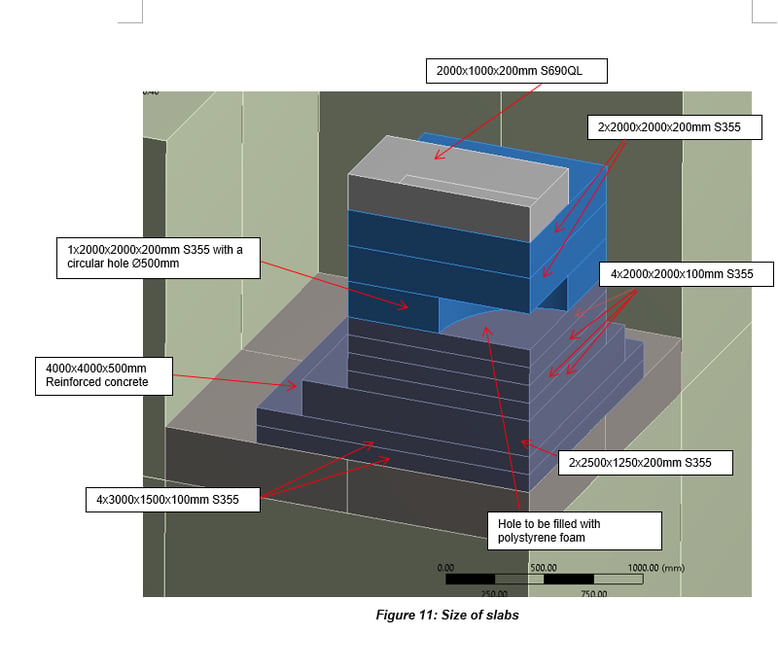
The solution was to cut a circular 1-metre hole in one of the upper plates and then force the pressure outwards. We also widened the lower plates to 3m x 3m followed by 2.5m x 2.5m plates and 2m x 2m plates. Finally top plates of 1m x 2m are installed.
A 400 mm strong reinforced concrete slab was casted to transfer the forces from the steel plinths and legs into the bedrock. A 1-metre thick reinforced concrete wall was casted around the plinths. The steel used for the plinths has a yield strength of 350 MPa except for the top plate, which has a value of 690 MPa. Subsequently, DNV-GL in Oslo evaluated and verified the conceptual design, and we received the final acceptance letter on September 20, 2017.
As mentioned, all CJ70 design units have the same footprint, but the steel plinths must be installed very precisely in the footprint, both horizontally and vertically. Therefore, we have compiled a very detailed drawing (verified by third-party company) of the theoretical footprint.
We must be able to have a touchdown on all nine steel plinths at the exact same time. The maximum deviation from the theoretical footprint should not exceed 40 mm in the horizontal plane. The height differences of the steel plinths within one leg should not exceed 18 mm, as this would cause RPD (Rack Phase Difference) problems.
After installation of the steel plinths and before opening of the dock gate, two independent survey companies finally verified the footprint. We managed to install the steel plinths perfectly within the tolerances.
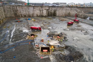
In the photo above, steel plinths are being submerged for forward leg – note the red top plate.
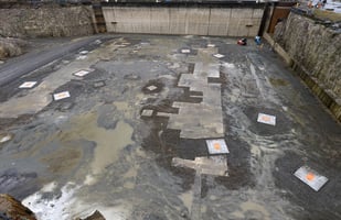
In the photo above, you see the dry dock after the nine steel plinths have been submerged in the dock bottom. The leg distance is 70 m.
The warranty surveyor shall accept the position of the CJ70 rig when properly towed into place. The warranty surveyor can only ‘accept’ the position of the rig if all rack plates are in full contact with the red top plates. The rig is now ready for jack-up in accordance with the operation manual. No preload will be required.
Having jacked up the rig to an adequate air gap, the clamps can be installed and the cantilever skidded out. Optionally, the dock gate can be installed and the dry dock emptied. When the dock is emptied is it possible to repair the spud cans or do other subsea repairs or modifications. The position of the rig is chosen to give the starboard crane maximum coverage of the quay. Once skidded out, the cantilever will be in over the end of the dock and the BOP can be exchanged.
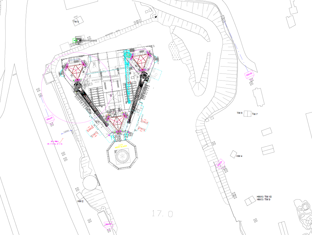
The GustoMSC CJ70 – X150 in proposed position in the dry dock.
